Amber, Industrial communication and control systems

Remote Monitoring & Control Systems

Menu navigation menu

  1. ML-417
  2. ML-E417
  3. ML-017SWARM, Satellite Logger
  4. ML Option Boards
  5. Power Editions
  6. HART Communication
  7. MQTT Serial Bridge
  8. Product Comparison
  9. Data Logger Power Consumption Calculator
  10. Remote Solar Powered Weather Station
  11. Logger Software and Manual
  12. Accessories
  13. Remote Configuration
 

The ML-x17 data logger is a small, ultra low power, cost effective data logger with built-in 4G Cat 1/LTE Cat M/NB-IoT cellular modem. This small data logger, is further provided with an internal temperature sensor, 8GB micro SD card and a 2FF SIM card slot. The data logger is available with several power provisions a/o: 3.6 Volt Lithium battery, 8..30V DC input or integrated solar panel with 3 x AA NiMH charger.

The data logger can acquire physical signals by 2 current loop inputs, 2 voltage inputs, 1 potentiometer input and 3 digital inputs. More or special inputs can be added by means of internal stackable option boards/converters. The data logger is provided with one serial port to capture measurements from ASCII, MODBUS, NMEA or SDI-12 compatible sensors. External sensors can be powered by the data logger itself, to prevent them to consume power while the data logger is a sleep. Up to 8 mathematical channels are available to calculate meaningful engineering values derived from sensor input values (e.g. a polynomial to calculate a flow from a stream level). Supports up to 8 aggregation channels (e.g. to record 2 or 10 minute windspeed averages sampled at 1Hz).


ML-417

The ML-417 data logger is a small, ultra low power, cost effective data logger with a built-in 4G cellular modem supporting LTE -M (Cat-M1), NB-IoT with 2G fallback. This small data logger, is further provided with an internal temperature sensor, 8GB micro SD card and a 2FF SIM card slot. The data logger is available with several power provisions a/o: 3.6 Volt Lithium battery, 8..30V DC input or integrated solar panel with 3 x AA NiMH charger.

The data logger can acquire physical signals by 2 current loop inputs, 2 voltage inputs, 1 potentiometer input and 3 digital inputs. More or special inputs can be added by means of internal stackable option boards/converters. The data logger is provided with one serial port to capture measurements from ASCII, MODBUS, NMEA or SDI-12 compatible sensors. External sensors can be powered by the data logger itself, to prevent them to consume power while the data logger is a sleep. Up to 8 mathematical channels are available to calculate meaningful engineering values derived from sensor input values (e.g. a polynomial to calculate a flow from a stream level). Supports up to 8 aggregation channels (e.g. to record 2 or 10 minute windspeed averages sampled at 1Hz).

Logged data can be pushed to a central host by HTTP(S), FTP(S), e-mail, secure TCP or MQTT at configurable intervals and optionally by satellite as well (Iridium SBD).

The ML-x17 is available in several editions and with 5 different cellular modems:

  • ML-417: 4G Global (LTE-M) with 2G fall-back
  • ML-E417: 4G Europe (LTE Cat 1) with 2G fall-back
  • ML-N417: 4G North-America (LTE Cat 1) with 3G fall-back

When equipped with the integrated solar panel a complete self providing remote monitoring station can be arranged, all you need is a logger and applicable sensor(s). This self providing cellular logger is costs saving, because you don"t need: a) solar panels, b) big batteries, c) cellular modem and d) encapsulating cabinet.


ML–417DS-LI, ML–417AD-LI,  ML–417ADS-LI A single D–Size 3.6V Lithium battery powerd ML–417 with blind cover (Using a SAFT–LSH20 battery is recommended)


ML–417DS-3LI, ML–417AD-3LI,  ML–417ADS-3LI Three D–Size 3.6V Lithium battery powerd ML–417 with blind cover (Using a SAFT–LSH20 battery is recommended)


 ML–417DS-SLA, ML–417AD-SLA,  ML–417ADS-SLA Integrated 12V Sealed Lead Acid/LiFePO4 battery  charger for external 21Voc solar panel


 ML–417DS-LFP, ML–417AD-LFP,  ML–417ADS-LFP  Integrated LiFePO4 cell charger for external 21Voc solar panel, 4x 18650 holder


ML–417DS-PV, ML–417AD-PV,  ML–417ADS-PV  A ML–417 with cover with integrated 1Wp tiny solar panel charging 3x AA 2100mAh NiMH batteries (Using LSD NiMH batteries like GP Recyko+ is recommended) 


ML–417DS-DC, ML–417AD-DC,  ML–417ADS-DC   An externally 8..30V DC powered ML–417 with blind cover and charging circuit for 3x AA NiMH (backup) batteries. This edition is very suitable to connect to a non continues external DC source


ML–417TFT A ML–417 with TFT screen


Features

  • Data logging
    › 1 second to 1 day intervals
    › regular, alarm and independent intervals
    › daily operation time bracket (e.g. 07:00AM to 20:00PM or 21:00PM - 06:00AM)

  • 5x analog inputs
    › 2x current loop inputs (0/4..20mA, 12bit resolution)
    › 2x voltage inputs (0..10V, 12bit resolution)
    › 1x voltage/potentiometer input (0..3300mV, 12bit, max. 10M) a/o to connect a wind direction sensor

  • 3x digital inputs (status, pulse counter or On-time meter) a/o to connect a flow meter, rain gauge or reed relay based wind speed sensor

  • Internal sensors (a/o battery, processor temperature, signal strength)

  • 8x calculation channels, to derive engineering values from sensed values using mathematical operators and functions (a/o cos, sin, atan2, ln, sqrt)

  • 8x aggregation channels, min/max, average, gust, std dev and up to 3 different percentiles sampled at 1Hz max.

  • 1x Serial port for connecting external sensors (RS-232, RS-485 or SDI-12)
  • Serial port drivers
    ASCII: Sensors autonomously outputting readable lines of numeric values
    MODBUS: Read-out value registers from MODBUS (RTU/ASCII) slave devices
    NMEA-0183: Sensors outputting standard and custom sentences
    SDI-12: Read-out of up to 16 devices with up to 20 parameters per device using aC!, aM!, aCx! or aMx! commands

  • 1x digital open collector alarm output to switch on a relay in case a parameter value is outside its limits (e.g. a high water level)

  • Accessories
    › Several stackable option boards 
    › JPEG camera CAM-2.0M
    › GPS receiver GPS-E3329

  • Built-in cellular data modem
    ML-217: 2G Global (Quad-band GPRS)
    ML-317: 3G Global (Penta-band)& 2G fall-back (Quad-band GPRS)
    ML-417: 4G Global (LTE-M)& 2G fall-back (Quad-band GPRS)
    ML-E417: 4G Europe (LTE Cat 1)& 2G fall-back (900/1800MHz)
    ML-N417: 4G North-America (LTE Cat 1)& 3G fall-back (850/1900Mhz)

  • 2FF (Class B) SIM-CARD slot
  • 8GB µSD-Card (file storage), 512kB FLASH (program storage), 64kB SRAM (runtime memory)
  • 60mA@3.6V average operating1) current during a duty cycle of less than 1 sec2) per log interval.
  • 250mA@3.6V average operating current during 20..60 sec. 3G data transfer
  • <80uA@3.6V sleep current
  • 12V@200mA switchable power outlet to power external sensors
  • Power supply
    › 3.6V DC input for internal Lithium battery3)
    › Optional 3xAA NiMH3) solar charger integrated in cover
    › Optional 8..30V DC-Adapter integrated in cover
  • Data push
    › 1 minute to 1 day intervals
    › regular and alarm intervals (direct push on alarm raise or fall)
    › daily operation time bracket (e.g. 07:00AM to 20:00PM or 21:00PM - 06:00AM)
    › native, JSON or CSV log files by HTTP(SSL/TLS), FTP(TLS Explicit), e-Mail(SMTP)4), secure TCP(AES-128) or MQTT
    › JPG pictures by HTTP(SSL/TLS), FTP(TLS Explicit), e-Mail(SMTP)4), secure TCP(AES-128) or MQTT
    › SBD messages by Iridium satellite modems (960x)
  • Alerts by SMS, e-Mail4) or MQTT
  • Configuration by USB (local) or secure TCP tunnel (remote)
  • Rugged and waterproof IP67 enclosure (130x120x75mm)
  • Optional pole mounting bracket
  • Integrated GSM antenna, external GSM antenna optional
  • Wide temperature operating range –30°C +75°C

1) 60mA if no external sensors need to be powered.
2) 3) Lithium batteries not included.
4) ML-417 has no eMail abilities.

Product sheets and additional files

view all files »

ML-x17ML-x17 Data Sheet

ML-x17 ManualML-x17 Manual

ML-x17 Power BoardML-x17 Power Board


ML-E417

The ML-E417 data logger is a small, ultra low power, cost effective data logger with a built-in 4G (Europe) cellular modem supporting LTE Cat 1 with 2G fallback. This small data logger, is further provided with an internal temperature sensor, 8GB micro SD card and a 2FF SIM card slot. The data logger is available with several power provisions a/o: 3.6 Volt Lithium battery, 8..30V DC input or integrated solar panel with 3 x AA NiMH charger. 

The data logger can acquire physical signals by 2 current loop inputs, 2 voltage inputs, 1 potentiometer input and 3 digital inputs. More or special inputs can be added by means of internal stackable option boards/converters. The data logger is provided with one serial port to capture measurements from ASCII, MODBUS, NMEA or SDI-12 compatible sensors. External sensors can be powered by the data logger itself, to prevent them to consume power while the data logger is a sleep. Up to 8 mathematical channels are available to calculate meaningful engineering values derived from sensor input values (e.g. a polynomial to calculate a flow from a stream level). Supports up to 8 aggregation channels (e.g. to record 2 or 10 minute windspeed averages sampled at 1Hz). 

Logged data can be pushed to a central host by HTTP(S), FTP(S), e-mail, secure TCP or MQTT at configurable intervals and optionally by satellite as well (Iridium SBD). 

The ML-x17 is available in several editions and with 5 different cellular modems:

  • ML-417: 4G Global (LTE-M) with 2G fall-back
  • ML-E417: 4G Europe (LTE Cat 1) with 2G fall-back
  • ML-N417: 4G North-America (LTE Cat 1) with 3G fall-back

When equipped with the integrated solar panel a complete self providing remote monitoring station can be arranged, all you need is a logger and applicable sensor(s). This self providing cellular logger is costs saving, because you don"t need: a) solar panels, b) big batteries, c) cellular modem and d) encapsulating cabinet.


ML–E417DS-LI, ML–E417AD-LI,  ML–E417ADS-LI A single D–Size 3.6V Lithium battery powerd ML–417 with blind cover (Using a SAFT–LSH20 battery is recommended)


ML–E417DS-3LI, ML–E417AD-3LI,  ML–E417ADS-3LI Three D–Size 3.6V Lithium battery powerd ML–417 with blind cover (Using a SAFT–LSH20 battery is recommended)


 ML–E417DS-SLA, ML–E417AD-SLA,  ML–E417ADS-SLA Integrated 12V Sealed Lead Acid/LiFePO4 battery  charger for external 21Voc solar panel


 ML–E417DS-LFP, ML–E417AD-LFP,  ML–E417ADS-LFP  Integrated LiFePO4 cell charger for external 21Voc solar panel, 4x 18650 holder


ML–E417DS-PV, ML–E417AD-PV,  ML–E417ADS-PV  A ML–417 with cover with integrated 1Wp tiny solar panel charging 3x AA 2100mAh NiMH batteries (Using LSD NiMH batteries like GP Recyko+ is recommended) 


ML–E417DS-DC, ML–E417AD-DC,  ML–E417ADS-DC   An externally 8..30V DC powered ML–417 with blind cover and charging circuit for 3x AA NiMH (backup) batteries. This edition is very suitable to connect to a non continues external DC source


ML–E417TFT A ML–417 with TFT screen


Features

  • Data logging 
    › 1 second to 1 day intervals 
    › regular, alarm and independent intervals 
    › daily operation time bracket (e.g. 07:00AM to 20:00PM or 21:00PM - 06:00AM) 

  • 5x analog inputs 
    › 2x current loop inputs (0/4..20mA, 12bit resolution) 
    › 2x voltage inputs (0..10V, 12bit resolution) 
    › 1x voltage/potentiometer input (0..3300mV, 12bit, max. 10M) a/o to connect a wind direction sensor 

  • 3x digital inputs (status, pulse counter or On-time meter) a/o to connect a flow meter, rain gauge or reed relay based wind speed sensor 

  • Internal sensors (a/o battery, processor temperature, signal strength) 

  • 8x calculation channels, to derive engineering values from sensed values using mathematical operators and functions (a/o cos, sin, atan2, ln, sqrt) 

  • 8x aggregation channels, min/max, average, gust, std dev and up to 3 different percentiles sampled at 1Hz max. 

  • 1x Serial port for connecting external sensors (RS-232, RS-485 or SDI-12)
  • Serial port drivers 
    › ASCII: Sensors autonomously outputting readable lines of numeric values 
    › MODBUS: Read-out value registers from MODBUS (RTU/ASCII) slave devices 
    › NMEA-0183: Sensors outputting standard and custom sentences 
    › SDI-12: Read-out of up to 16 devices with up to 20 parameters per device using aC!, aM!, aCx! or aMx! commands 

  • 1x digital open collector alarm output to switch on a relay in case a parameter value is outside its limits (e.g. a high water level) 

  • Accessories 
    › Several stackable option boards 
    › JPEG camera CAM-2.0M 
    › GPS receiver GPS-E3329 

  • Built-in cellular data modem 
    › ML-217: 2G Global (Quad-band GPRS) 
    › ML-317: 3G Global (Penta-band)& 2G fall-back (Quad-band GPRS) 
    › ML-417: 4G Global (LTE-M)& 2G fall-back (Quad-band GPRS) 
    › ML-E417: 4G Europe (LTE Cat 1)& 2G fall-back (900/1800MHz) 
    › ML-N417: 4G North-America (LTE Cat 1)& 3G fall-back (850/1900Mhz) 

  • 2FF (Class B) SIM-CARD slot
  • 8GB µSD-Card (file storage), 512kB FLASH (program storage), 64kB SRAM (runtime memory)
  • 60mA@3.6V average operating1) current during a duty cycle of less than 1 sec2) per log interval.
  • 250mA@3.6V average operating current during 20..60 sec. 3G data transfer
  • <80uA@3.6V sleep current
  • 12V@200mA switchable power outlet to power external sensors
  • Power supply 
    › 3.6V DC input for internal Lithium battery3) 
    › Optional 3xAA NiMH3) solar charger integrated in cover 
    › Optional 8..30V DC-Adapter integrated in cover
  • Data push 
    › 1 minute to 1 day intervals 
    › regular and alarm intervals (direct push on alarm raise or fall) 
    › daily operation time bracket (e.g. 07:00AM to 20:00PM or 21:00PM - 06:00AM) 
    › native, JSON or CSV log files by HTTP(SSL/TLS), FTP(TLS Explicit), e-Mail(SMTP)4), secure TCP(AES-128) or MQTT 
    › JPG pictures by HTTP(SSL/TLS), FTP(TLS Explicit), e-Mail(SMTP)4), secure TCP(AES-128) or MQTT 
    › SBD messages by Iridium satellite modems (960x)
  • Alerts by SMS, e-Mail4) or MQTT
  • Configuration by USB (local) or secure TCP tunnel (remote)
  • Rugged and waterproof IP67 enclosure (130x120x75mm)
  • Optional pole mounting bracket
  • Integrated GSM antenna, external GSM antenna optional
  • Wide temperature operating range –30°C +75°C

1) 60mA if no external sensors need to be powered.
2) 3) Lithium batteries not included.
4) ML-417 has no eMail abilities.

Product sheets and additional files

view all files »

ML-x17 ManualML-x17 Manual

ML-x17 Power BoardML-x17 Power Board


ML-017SWARM, Satellite Logger

he ML-017SWARM is a small, cost effective data logger with built-in satellite modem suitable for data transfer over the Swarm low earth orbiting satellite constellation. The Swarm constellation has real global coverage enabling to monitor environmental phenomena and precious resources all over the planet affordably. This small data logger in rugged weatherproof enclosure, is provided with an industrial grade microSD card, re-chargeable battery slots and integrated charger to be powered from a small external solar panel. Hook-up sensors of your choosing to assemble a self-sustaining monitoring station that can be deployed anywhere around the globe.

The data logger can acquire physical signals by 2 current loop inputs, 2 voltage inputs, 1 potentiometer input and 3 digital inputs. More or special in/outputs can be added by means of internal stackable option boards/converters. The data logger is provided with one serial port to capture measurements from ASCII, MODBUS, NMEA or SDI-12 compatible sensors. External sensors can be powered by the data logger itself, to prevent them to consume power while the data logger is a sleep. Up to 8 mathematical channels are available to calculate meaningful engineering values derived from sensor input values (e.g. a polynomial to calculate a flow from a stream level). Supports up to 8 aggregation channels (e.g. to record 10 minute windspeed averages sampled at 1Hz). The data logger can record up to 64 different parameters/channels (to SD-Card) of which a maximum of 15 can be marked-up for satellite transfer. Up to 750 satellite data packets can be transferred per month, so about 1 per hour. Data compaction is used to squeeze as much as possible data into a single 192 byte packet (typically 6 time series of about 10 channels).

Transferred data will be securely stored in a cloud storage called the Hive and can also directly be passed to the Sensori IoT-platform to present your sensor data and gain valuable insights.

Features

  • Data logging
    › 1 minute to 1 day intervals.
    › Regular, alarm and independent intervals.
    › Daily operation time bracket (e.g. 07:00AM to 20:00PM or 21:00PM - 06:00AM)
    › 8GB industrial grade micro SD-Card.

  • Data push to the Hive and Sensori
    › 1 hour to 1 day enqueue intervals.
    › Daily operation time bracket (e.g. 07:00AM to 20:00PM or 21:00PM - 06:00AM)
    › Up to 15 channels can be marked up for transfer.
    › Payload compaction. Typically 6 time series of 10 channels will fit a single data packet, equivalent to recording 10 channels with a 10 minute interval and a 1 hour enqueue interval.
    › Enqueued packets are transferred when a swarm passes by.

  • 5x analog inputs
    › 2x current loop inputs (0/4..20mA, 12bit resolution)
    › 2x voltage inputs (0..10V, 12bit resolution)
    › 1x voltage/potentiometer input (0..3300mV, 12bit, max. 10M) a/o to connect a wind direction sensor.

  • 3x digital inputs (status, pulse counter or On-time meter) a/o to connect a flow meter, rain gauge or reed relay based wind speed sensor.

  • Internal sensors (a/o battery, processor temperature, GPS, signal strength)

  • 8x calculation channels, to derive engineering values from sensed values using mathematical operators and functions (a/o cos, sin, atan2, ln, sqrt)

  • 8x aggregation channels, min/max, average, gust, std dev and up to 3 different percentiles sampled at 1Hz max.

  • 1x Serial port for connecting external sensors (RS-232, RS-485 or SDI-12)
  • Serial port drivers
    › ASCII: Sensors autonomously outputting readable lines of numeric values.
    › MODBUS: Read-out value registers from MODBUS (RTU/ASCII) slave devices.
    › NMEA-0183: Sensors outputting standard and custom sentences.
    › SDI-12: Read-out of up to 16 devices with up to 20 parameters per device using aC!, aM!, aCx! or aMx! commands.

  • 1x digital open collector alarm output to switch on a relay in case a parameter value is outside its limits (e.g. a high water level)

  • Accessories
    › Several stackable option boards

  • Built-in satellite modem
    › Swarm constellation compatible.
    › 192 byte data packet payload size.
    › 137-138 MHz downlink, 148-150 MHz uplink frequency.
    › 22cm SMA-male coiled 1/4 wave antenna, 2.0 dBi gain.
    › Place antenna outdoors with clear view to the sky.
    › Place antenna >=1m above the ground or solid surfaces.
    › Keep antenna away from RF noise sources (RSSI < -90dBm).
    › Integrated GPS antenna, external GPS antenna optional.

  • Power consumption
    › 60mA@3.6V average operating1) current during a duty cycle of less than 1 sec2) per log interval.
    › <80uA@3.6V sleep current.
    › 50mA@3.6V additional when the Swarm modem is active3
    › 12V@200mA excitation to power external sensors.

  • Power supply
    › To be powered from a 36 cell 12V (21Voc) solar panel 5Wp or more.
    › Integrated LiFePO4 3.2V battery4) charger.
    › State of Charge (3.1V<5%, 3.2V<20%, 3.25V<50%, 3.3V<90%, 3.4V<100%)
    › 2x 18650 battery slots, up to 3600mAh@3.2V capacity

  • Alarming
    › Open collector output (max. 100mA sink current)

  • Configuration by 
    › USB (Windows PC or Android device)
    › Wireless by Android BLE when equipped with ML-OU-BLE board.

  • Enclosure
    › IP67 (30min@1m), 150x120x90mm, 420g.
    › UV stabilized polycarbonate.
    › Wide temperature operating range –30°C to +75°C
    › Optional pole mounting bracket

1) 60mA if no external sensors need to be powered.
2) 3) Stays active till all enqueued packets are transferred, can take hours (see: Swarm Pass Checker)
4) LiFePO4 or NiMH batteries not included.


ML Option Boards

Option boards can be used to add additional inputs/features to an ML-x17 data logger or to perform signal conditioning. You can mechanically stack up to 3 option boards, but only one board per category ID (CID). Some boards are having a switch to choose a different CID, so you can stack multiple similar boards. Converter boards (OC) don"t have CID"s and you can stack as many OC-boards as mechanical feasible. OC-boards don"t make use of the internal control bus, but are wired to existing inputs/outputs/ports.


Power Editions


High Capacity Lithium Thionyl Chloride - Non Rechargeable


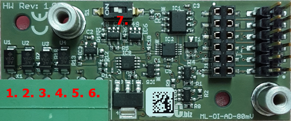
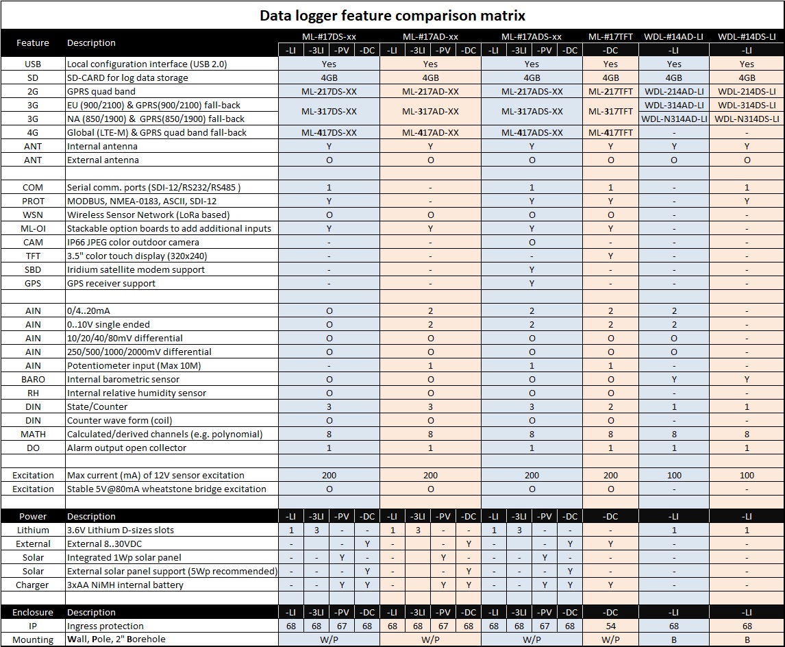
ML-x17DS-LI, ML-x17AD-LI, ML-x17ADS-LI
A D-Size 3.6V Lithium battery powered ML-x17 with blind cover (Using a SAFT-LSH20 or GEBC-ER34615M battery is recommended)

This edition is best suitable for monitoring with longer log intervals >=1h and transfer intervals >=4h.

ML-x17DS-3LI, ML-x17AD-3LI, ML-x17ADS-3LI
Same as above, but equipped with D-size holders to host up to 3 Lithium SAFT LSH20 batteries safely, with a combined lossless capacity of 39000mAh

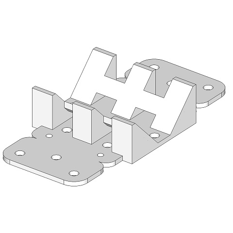
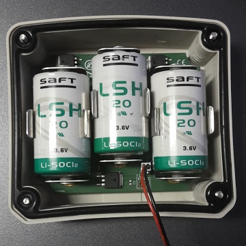
The ML-COVER-3LI is a power provision cover fitting our ML-x17 off-grid 2G/3G/4G data loggers to power a data logger from up to 3 D-Size Lithium SAFT LSH20 batteries safely, with a combined lossless capacity of 39000mAh.

Although our off-grid data loggers are designed to be as low power as possible, running it from just one single Lithium battery, due to the power demand of mobile communication, has its limits. If you have an application requiring 1 or 2 remote data updates each day a single battery powered data logger can run for years. When you need multiple remote data updates each day, then our data logger with tiny integrated 1Wp solar panel has proven to be a very suitable solution, assuming the data logger can be mounted outside facing the sun. If for obvious reasons a solar powered solution is not possible, then you could consider the use of a lithium battery pack. This is however something to consider with caution!

Lithium batteries are having a high energy density and when used without caution, they can turn into dangerous devices. If you put multiple Lithium batteries with all having the same state of charge in parallel, then it could work, but using it like that is strictly discouraged by the battery manufacturer.

The common save way to put batteries in parallel is by using diodes, but they come with a price. Although battery capacity is specified in mAh’s, it stores energy (mWh’s) and the diodes will dissipated a serious portion of this precious energy. The nominal voltage of a SAFT LSH20 is 3.6V@2mA, but during data logger operation load the voltage drops to 3.5V. A Shottky diode has a forward voltage of 0.3V, so a single diode will dissipate 8.5% of the stored energy. And because the voltage towards the logger drops, the electronics need to draw at least 8.5% more current to compensate the voltage drop. So using diodes will virtual reduce the capacity of a battery by almost 20%. When placing two Lithium’s (with two diodes) in parallel, the capacity increase will be about 65% instead of the expected 100%.

The solar energy industry is experiencing the same kind of problems as blocking and by pass diodes are causing significant system losses. The semi-conductor industry reacted by developing a so called “smart diode”. A “smart diode” is a chip containing comparators, a FET and a regular diode. When the input voltage is lower than the output voltage the FET will not conduct, the battery will not contribute to the energy demand and the regular diode will block the possible reflux from other batteries. When the input voltage is higher than the output voltage, the FET will start to conduct and the battery will contribute to the energy demand. The forward voltage over the FET is just 26mV instead of 300mV.

The ML-COVER-3LI is making use of such “smart diodes” and having three D-size battery holders. You can choose the insert one, two or three Lithium batteries to reach a combined capacity of 39000mAh. When even more capacity is required, multiple boards can be arranged in parallel as well.

Please use our online Data logger power consumption calculator to estimate the battery life of your application.

Specifications
  • Power bank
    › 39000 mAh capacity (when using 3 batteries).
    › 3x D-size havy duty battery holder.
    › 3x "smart" diode for lossless safe operation.
    › Reverse battery protection.
    › Designed for 3.6V SAFT-LSH20 or GEBC-ER34615M lithium batteries or equivalents only.
    › Batteries are not included.

  • Enclosure
    › IP68 (30min@2m) waterproof enclosure.
    › UV stabilized polycarbonate.
    › 130x120x40mm, 275g.
    › Silicone gasket
    › 4x stainless steel (A2/W4/304) M4 bolt (25mm)


Solar Powered Editions


ML-x17DS-PV, ML-x17AD-PV, ML-x17ADS-PV
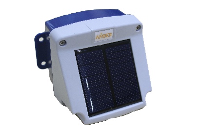
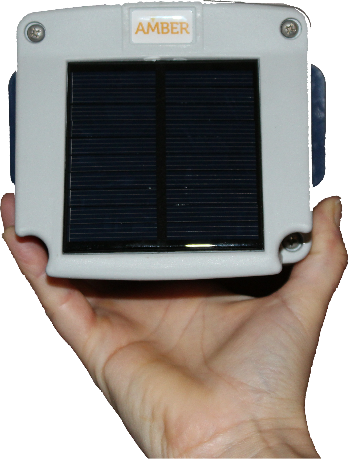
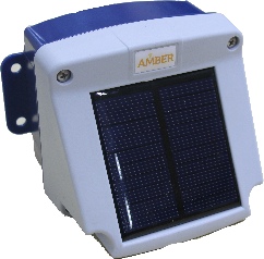
An ML-x17 with cover with integrated 1Wp tiny solar panel charging 3x AA NiMH batteries (Using LSD NiMH batteries with a minimum capacity of 2000mAh, like GP Recyko+ or Sanyo Eneloop, is strongly recommended). The batteries are protected against damage by over charging by the dimension of the panel and from damage by depletion by temporarily switching off the power to the logger, giving the sun the chance to replenish the batteries.

The PV-cells are encapsulated in ETFE sheet, which is the perfect material as it is heat resistant (up to 150°C) and does not deteriorate by UV-rays (UV-rays are passed thrue and contribute to the energy harvesting). The PV-cover is rather maintenance free as the ETFE surface is non-sticky and therefor self-cleaning (dust is easily blown off by wind and dirt washed away by a rain shower).

This edition is best suitable for monitoring with moderate log intervals >=5 min and transfer intervals >=15 min.


ML-x17DS-LFP, ML-x17AD-LFP, ML-x17ADS-LFP


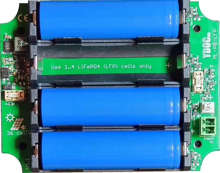
An ML-x17 powered from 1 to 4 LiFePO4 18650 3.2V cells. The integrated charger can be used to charge the internal batteries from an external 36-cells 12Vnom/21Voc solar panel. 

This edition is best suitable for applications with power hungry sensors for monitoring with low log intervals

The ML-COVER-LFP is a power provision cover fitting our ML-x17 off-grid 2G/3G/4G data loggers. An ML-x17 can be powered from 1 to 4 LiFePO4 18650 3.2V cells, which can be charged by connecting an external solar panel.

This power provision might be a convenient alternative, if your application needs a bit more energy storage than three AA NiMH batteries can provide, but you want to avoid using an external 12V battery.

LiFePO4 is a stable and safe battery chemistry with an excellent cycle life (over 1000 cycles at 100% DOD and thousands at 80% DOD). The energy round trip efficiency is much better than that of NiMH or Lead Acid batteries, so you can yield more energy from a same sized solar panel.

Please use our online Data logger power consumption calculator to estimate the battery life of your application.

Specifications
  • Batteries (not included)
    › Chemistry: LiFePO4 (LFP)
    › Cell voltage: 3.2V Nominal
    › Cell type: 18650
    › Holders: 4, up to 7200mAh (23Wh)

  • Charge controller
    › Cell over charge protection
    › Cell charge temperature protection
    › Cell low voltage protection (auto output switch-off at 2.5V)

  • Solar input (X1)
    › Number of cells: 36
    › Nominal voltage: 12V
    › Open circuit voltage: 21V recommended (18V..28V)

  • Outputs (X2):
    › 3.2V to power the data logger.1)

  • Enclosure part
    › IP68 (30min@2m) waterproof enclosure.
    › UV stabilized polycarbonate.
    › 130x120x40mm, 275g.
    › Silicone gasket
    › 4x stainless steel (A2/W4/304) M4 bolt (25mm)

1) You have to set the "Battery (protection & lifespan)" property in the ML-x17 to "Rechargeable LFP" to prevent the data logger to fall into a continuous deep sleep (NiMH battery protection mode)!


ML-x17DS-SLA, ML-x17AD-SLA, ML-x17ADS-SLA


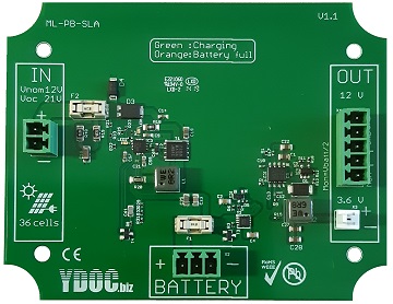
An ML-x17 to be powered from an external 12V Sealed Lead Acid/LiFePO4 battery, the integrated charger can be used to charge the 12V battery from an external 36-cells 12Vnom/21Voc solar panel. 

This edition is best suitable for applications with power hungry sensors, sensors that require continuous power or for monitoring with fast transfer intervals <=5 min.

The ML-COVER-SLA is a power provision cover fitting our ML-x17 off-grid 2G/3G/4G data loggers to power a data logger from a 12V battery and to charge the battery from an external solar panel.

We designed our remote data loggers to be cost effective and low power, but as they are feature rich and practical in use as well, we see a growth in deployment in more power demanding monitoring applications. Think of applications with power hungry sensors or sensors that need to be powered continuously. In such applications a bigger battery, then just three AA NiMH batteries, is inevitable. An external 12V battery could already be connected to an ML-x17yy-DC data logger, but it required an additional charge controller. We have designed a new power supply option with integrated 12V battery charger to cut-out the cost of an external charger and to reduce installation costs as well, all you need is an ML-x17yy-SLA, your sensors, an external 12V battery and a solar panel.

Please use our online Data logger power consumption calculator to estimate the battery life of your application.

Specifications
  • Charge controller
    › Battery over charge protection
    › Battery low voltage protection (auto switch-off/on outputs at 11V)
    › Charge current: 2A maximum

  • Solar input (X1)
    › Nominal voltage: 12V
    › Open circuit voltage: 21V recommended, 30V maximum

  • Battery input (X2)
    › Voltage: 12V nominal
    › Supported chemistry: SLA (Sealed Lead Acid) or LiFePO4
    › Capacity: 2.7Ah minimum, no maximum

  • Outputs (X3 & X4):
    › Regulated 3.6V to power the data logger
    › Unregulated 12V (from battery) to continuously power external devices 1)2)
    › Battery voltage monitoring 3)

  • Enclosure part
    › IP68 (30min@2m) waterproof enclosure.
    › UV stabilized glass fiber enforced poylamide66.
    › 130x120x40mm, 275g.
    › Silicone gasket
    › 4x stainless steel (A2/W4/304) M4 bolt (25mm)

1) Sensors that only require power during sampling should be powered from the 12V power switch of the ML-x17.

2) Sensors that require continuous power could be connected to the terminals of a 12V battery directly as well, but its better to connect them to the outputs of the charger board as they will be switched of in case of a depleted battery to avoid damaging the battery.

3) The battery voltage monitoring pin reflects the battery voltage divided by 2 to be able to connect it to a 10V analog input of an ML-x17 (Don"t forget to multiply the measured value by 2 again).

Tip) Small capacity 12V batteries like the Pbq 2.9Ah could fit into an empty ML-x17 enclosure (ML-BOX + ML-COVER), if their dimensions stay within 92x74x64, 112x74x64 or 92x98x64 mm.


DC Powered Editions


ML-x17DS-DC, ML-x17AD-DC, ML-x17ADS-DC
An externally 8..28V DC powered ML-x17 with blind cover.

This edition is best suitable when a reliable external DC source is easily available or for monitoring with low log intervals
  

ML-x17DS-DC-LI, ML-x17AD-DC-LI, ML-x17ADS-DC-LI
As above but with a D-Size 3.6V Lithium back-up battery holder (Using a SAFT-LSH20 or GEBC-ER34615M battery is recommended).

This edition is best suitable when a external DC source is easily available but suffering from occasional outages.
  
ML-x17DS-DC-NM, ML-x17AD-DC-NM, ML-x17ADS-DC-NM
An externally 8..28V DC powered ML-x17 with blind cover and charging circuit for 3x AA NiMH (backup) batteries. The charging circuit protects the batteries from damage by over charging.

This edition is best suitable when a (non continues) external DC source is easily available or for monitoring with low log intervals 

Tips: When using solar panels we recommend to use panels with a VOC of 17V or higher as well as panels not smaller than 3Wp. We also recommend to use LSD NiMH AA batteries with the highest capacity available (2600 mAh).
 

HART Communication

YDOC ML-OI-AX-HART option Board


The ML-x17 data logger can be equipped with an ML-OI-AX-HART input board to be able to connect HART compatible sensors/indicators.

The HART Communication Protocol (Highway Addressable Remote Transducer) is a hybrid analog+digital industrial automation open protocol. Its most notable advantage is that it can communicate over legacy 4–20 mA analog instrumentation current loops, sharing the pair of wires used by the analog-only host systems. Although its dating back to the mid-1980s, the HART protocol is still one of the most popular protocols used in process and instrumentation systems.

The ML-OI-AX-HART board can be used in both point-to-point (single sensor) as in multi-drop (multiple sensors) mode. The board has a 12V excitation and an internal load resistor in the ground loop, it requires just two wires to both power and communicate with a sensor.

The 12V wire should be connected to the "Loop +" input of a sensor and the returning wire between the "Loop -" output of a sensor and the "Loop +" input of the ML-OI-AX-HART board. In case of connecting multiple sensors (multi-drop), just connect all sensors in parallel.

The input board supports up to 8 channels, where each channel can be linked to the address of a connected sensor and to one of the values given by it (the current loop, primary, secondary, tertiary or quaternary value). The board has a configuration feature to scan for connected sensor ID"s.

Note: When a sensor is powered from the board"s or ML-x17 power switch, don"t forget to specify a sufficient power-up time, which can be tens of seconds depending on the used sensor.

Specifications
  • Protocol: HART
  • Topology: Point-to-Point & Multi-Drop
  • Power switch: 12V
  • Load resitor: Internal (270 Ohm)
  • Input channels: 8
  • Sensors: Up to 8
  • Values: Current loop, primary, secondary, tertiary or quaternary
 

MQTT Serial Bridge

communication bridge

Although our data loggers can capture measurements from various serial devices or smart sensors by standard serial communication protocols (e.g MODBUS, NMEA-0183 or SDI-12), the data logger itself has no knowledge about how to apply changes to these often proprietary devices.

The integrated MQTT serial communication bridge, which we call "MQTT-Com-tunnel", enables to send/receive1) data to/from serial devices connected to the data logger remotely(e.g. to reset something in a device or to occasionally give a sensor a command to do some cleaning or internal house keeping).

Commands can be send to the serial sensor (RS232/RS485/SDI-12) or accessory (RS232) port on the main PCB as well as on option boards. The (binary) data contained in the MQTT payload will be passed transparently 1 to 1 to the concerned serial device and the response will be replied as (binary) payload 1 to 1 as well, it’s up to the MQTT-client to format and interpret the data to/from the serial device (which could be MODBUS/RTU, SDI-12, NMEA-0183 or any other protocol).

Commands can be initiated from an automated task on some server, but they can also be initiated manual from an MQTT smart phone app (e.g. the Android app: MQTT Terminal)

When a COM-tunnel message is received destined for a device connected at a serial sensor port and the device requires power from the 12V sensor power switch, the data logger will switch on the 12V power and wait a certain warm-up time before sending the command to the device. The warm-up time will not be applied in case of sequential commands in the same MQTT-session.

When a COM-tunnel message is received destined for a device connected at an accessory port and the device requires power from the 5V accessory power switch, the data logger will switch on the 5V power and wait a certain warm-up time before sending the command to the device. The warm-up time will not be applied in case of sequential commands in the same MQTT-session.

After sending data to the serial device, the data logger will wait max 3 seconds for reply from the connected device. In case of no response, the data logger will publish an MQTT message with empty payload. If the serial device replies, the reply is considered complete after a character silence time of 0.25s. The data logger will publish an MQTT message with the full 1 to 1 (binary) reply as the payload.

Note: Be aware that communication is not instant as the data logger is not continuously connected with the MQTT-broker. It connects frequently, according to your schedule, to publish measurements.

Topics:

An MQTT-client should format a command publishing topic as follows:

“YDOC/<device serial number>/comtx/<port>[/<client defined sup-topics]” (QoS=1)

Where <port> can be (if installed and configured in the data logger):

  • “sp1”, the serial sensor port on the main PCB
  • “ap1”, the accessory port on the main PCB
  • “sp2”, the serial sensor port on an option board
  • “ap2”, the accessory port on an option board

The MQTT-client can specify optional sub-topics for its own internal management, the used sub-topics are also included in the MQTT reply messages. Such sub-topics could be used for grouping or matching commands with replies (e.g. by using some sequence# as sub-topic).

Example: “YDOC/99091660/comtx/sp1” or “YDOC/99091660/comtx/sp1/S123/METEO/”

The data logger will publish the reply with the same topic as the command, but will replace the text “comtx” with “comrx”

Example: “YDOC/99091660/comrx/sp1/S123/METEO/”)

An MQTT-client can use wild-cards to subscribe to any COM-tunnel message from any data logger within the scope of the MQTT-account, by subscribing to: “YDOC/+/comrx/#” (QoS=1)

Limits:

  • Topic size: 128 characters
  • Payload size: 256 bytes for commands, 512 bytes for replies
  • Device reply timeout: 3s (The device should answer within 3 sec)
  • Silence time: 0.25s (A reply is considered complete after a communication silence time of 0.25s)
 

Product Comparison


Data Logger Power Consumption Calculator

Data Logger Power Consumption Calculator

Data Logging   Daily consumption
Data logging interval min.    
Number of parameters to log      
External sensor(s) power on time sec. (warm-up + sample time)    
External sensor(s) current @12V mA    
Potentiometer input kOhm (0 = not used)   Logging - mWh
Accessory   Daily consumption
Accessory    
Accessory logging interval min.    
Picture Format   Logging 0 mWh
Data transfer Payload   Daily consumption
Modem type    
Transfer protocol TLS    
Transfer interval min. 576 kB/month   Transfer 0.00 mWh
Energy source   Daily balance
Battery type   Total consumption - mWh
Battery capacity1) mAh (- mWh)    
Solar panel1) 2)      
Yearly in-plane irradiation3) kWh/m2   Average solar yield - mWh
Average monthly irradiation3)
during the darkest 3 months
kWh/m2   Avg. dark days yield - mWh
Average temperature
during the darkest 3 months
°C        
   
Estimated batt. life Indefinite Days Indefinite Years   Worst case batt. draw - mWh
1) The calculations are taking the deterioration of the solar panel and rechargeable batteries already into account. In case of using our solar panel, use LSD NiMH rechargeables with a capacity of at least 2000mAh only (We advise GP-Recyko).

2) The 60° slope of our 1Wp solar panel is an optimum to get through the darkest months in Northern Europe. Outside the tropics you need to face the panel to the equator, inside the tropics you need the face the panel eastwards (Azimuth = -90º) or westwards (Azimuth = +90º).

3) You can use the EU-PVGIS tool to determine the yearly and monthly in-plane irridation in kWh/m2 at the optimum Azimuth for our 60º sloped panel in your region. If your region is outside the data coverage, choose a matching GPS latitude in side the data covered area.

In the EU-PVGIS tool:
  • Double click your location in the Map
  • Specify the slope of your solar panel (60º for our integrated 1Wp panel)
  • Specify the best Azimuth for your situation/region
  • Click the "Visialize results"-button
  • Note the "Yearly in-plane irridiaton"-value
  • Click the "Radiation"-button.
  • Calculated the monthly average over the 3 darkest months
 

Remote Solar Powered Weather Station

You can arrange a really low power and cost effective remote automated weather station by combining meteo sensors of your favourite brand with our ML-x15AD(S)-PV  3G/GPRS data logger with integrated solar panel. The arranged AWS is very cost effective because all you need is our reasonably priced data logger and applicable meteo sensors of your choosing, you don"t need a big solar panel, big battery, charger or encapsulating cabinet. 

Common parameters monitored by an AWS are: Air temperature, humidity, barometric pressure, precipitation, wind speed and direction. 

Temperature, humidity and barometric pressure 

Air temperature, humidity and pressure are relatively slow rising and declining parameters and recording their instant values every 5 or 10 minutes is enough for weather monitoring that does not have to be in compliance with strict (governmental) regulations. To preserve power, the data logger will power the sensors during sampling only. The sensors of your choosing can be connected to the analog inputs or SDI-12 interface of the data logger. 

Precipitation 

Precipitation can be recorded by connecting a classical tipping bucket rain gauge to one of the digital inputs of the data logger. Counting bucket pulses draws negligible power from the data logger"s internal batteries. The data logger records rain intensity, quantity and cumulative quantity. 

Wind speed and direction 

Wind is a very fluctuating subject and an accurate impression can not be given by taking a sample once a while, it requires continues sampling. To maintain low power consumption you have to pick your wind sensors with care as you have to choose sensors that draw negligible power from the data logger"s internal batteries. 

For wind speed you have to choose a classical powerless anemometer with magnet(s) and reed switch output, where each revolution of the anemometer causes one or multiple reed switch closures. The reed switch output can be connected to one of the digital inputs of the data logger. The data logger can sample the wind speed at 1Hz and record aggregated values (average, minimum, maximum, gust and standard deviation) every data log interval (e.g. 2 or 10 minutes). 

Examples of such anemometers are: Davis D6410Skye A100R or Synchrotac SYN710-1980 

For wind direction you have to choose a classical windvane with potentiometer output, which can be connected to the resistance input of the data logger. The data logger can sample the wind direction at 1Hz and record aggregated values (average, minimum, maximum and standard deviation) every data log interval (e.g. 2 or 10 minutes). 

Examples of such wind vanes are: Davis D6410Skye W200P or Synchrotac SYN710-2900 

Note 1: The higher the potentiometer resistance, the lower the power consumption. To decrease consumption you could consider to add resistors in series with the potentiometer of the wind vane (one in the ground wire and an equal one in the excitation wire to the windvane). Adding a resistance equal to the wind vane"s potentiometer, will decrease the windvane"s consumption by 50%. Its preferred to have a total resistance of at least 3k Ohm

Note 2: After connecting a wind vane with additional series resistors, its recommended to perform a 2 point user calibration (e.g. one point at 90° and one at 270°) 


Product sheets and additional files

view all files »

Remote Solar Weather StationDavis D6410 Remote Solar Weather Station Configuration Instructions


Logger Software and Manual

Please find here the latest firmware and Terminal software for the Low Power Data Logger Range

Product sheets and additional files

view all files »

ML-215/315 Logger Firmware

ML-2013 Firmware

WDL-214/314 Firmware

Data Logger Terminal Application

Manual

ML-217/317/417 Firmware


Accessories

Battery Power Bank

GPS Receiver

IP66 Weatherproof Low Power Camera 0.3M

IP66 Weatherproof Low Power Camera 1.3M

Satelitte Communication Transceiver

Mounting 


ML-COVER-3LI – Lithium Battery Power Pack - 3 x SAFT LSH20 (39000mAh)

The ML-COVER-3LI is equipped with D-size holders to host up to 3 Lithium SAFT LSH20 batteries safely, with a combined lossless capacity of 39000mAh. The ML-COVER-3LI is a replacement cover for our ML-x15 off-grid 3G/GPRS data loggers. 

Although our off-grid data loggers are designed to be as low power as possible, running it from just one single Lithium battery, due to the power demand of mobile communication, has its limits. If you have an application requiring 1 or 2 remote data updates each day a single battery powered data logger can run for years. When you need multiple remote data updates each day, then our data logger with tiny integrated 1Wp solar panel has proven to be a very suitable solution, assuming the data logger can be mounted outside facing the sun. If for obvious reasons a solar powered solution is not possible, then you could consider the use of a lithium battery pack. This is however something to consider with caution! 

Lithium batteries are having a high energy density and when used without caution, they can turn into dangerous devices. If you put multiple Lithium batteries with all having the same state of charge in parallel, then it could work, but using it like that is strictly discouraged by the battery manufacturer. 

The common save way to put batteries in parallel is by using diodes, but they come with a price. Although battery capacity is specified in mAh’s, it stores energy (mWh’s) and the diodes will dissipated a serious portion of this precious energy. The nominal voltage of a SAFT LSH20 is 3.6V@2mA, but during data logger operation load the voltage drops to 3.5V. A Shottky diode has a forward voltage of 0.3V, so a single diode will dissipate 8.5% of the stored energy. And because the voltage towards the logger drops, the electronics need to draw at least 8.5% more current to compensate the voltage drop. So using diodes will virtual reduce the capacity of a battery by almost 20%. When placing two Lithium’s (with two diodes) in parallel, the capacity increase will be about 65% instead of the expected 100%. 

The solar energy industry is experiencing the same kind of problems as blocking and by pass diodes are causing significant system losses. The semi-conductor industry reacted by developing a so called “smart diode”. A “smart diode” is a chip containing comparators, a FET and a regular diode. When the input voltage is lower than the output voltage the FET will not conduct, the battery will not contribute to the energy demand and the regular diode will block the possible reflux from other batteries. When the input voltage is higher than the output voltage, the FET will start to conduct and the battery will contribute to the energy demand. The forward voltage over the FET is just 26mV instead of 300mV. 

The ML-COVER-3LI is making use of such “smart diodes” and having three D-size battery holders. You can choose the insert one, two or three Lithium batteries to reach a combined capacity of 39000mAh. When even more capacity is required, multiple boards can be arranged in parallel as well. 


CAM–SO.3M – Camera – Single Lens 0.3M JPEG camera with 5M night Vision

 The CAM-x0.3M is a low power weatherproof camera that can be connected to an ML-x15ADS-PV or ML-2013.html data logger. The data logger can be configured to record snapshots at regular intervals (e.g. once or multiple times per day) and at alarm raise and fall conditions (e.g. at flooding a river) As we are acting in the low power domain, our camera solution has to be low power as well! Therefor remote streaming of video or taking super hires pictures at high speed is beyond the goal of our solution. The data logger can deliver the JPEG pictures in your e-mail box or to an FTP-server. The JPG pictures can also be transferred as "Digital Assets" to ydocInsights.

The CAM-B0.3M is provided with IR LED"s to be able to take B/W pictures at night as well as color pictures during daylight. The camera has only one (IR) lens and therefore the colors are deviating from the real colors, please consider the CAM-C0.3M camera if true colors are required (bad pictures when dark). Our data loggers can be configured to take pictures during a specified daily time bracket only (e.g. 07:00AM to 20:00PM or 21:00PM - 06:00AM) The CAM-x0.3M is meant to monitor objects at close distance and has a 90° angle of view and a night vision of max 5m. We recommend our CAM-D1.3M camera for monitoring objects at further distance. The CAM-x0.3M can take pictures up to 640x480 pixels. Taking a 640x480 picture draws 2.5mAh from the batteries, please use our online Data logger power consumption calculator to estimate the battery life of your application.

Specifications

  • CMOS image sensor

  • Image resolution
    › 160 x 128 pixels
    › 320 x 240 pixels
    › 640 x 480 pixels

  • JPEG image compression

  • IR lens with 3.6mm focus length

  • 90° angle of view

  • Maximum 5m night vision

  • Automatic white balance, exposure and gain control

  • RS-232 serial interface
    › To ML-x15ADS accessory port only
    › To ML-2013 one of the two RS-232 ports

  • Power supply (+5V maximum!)
    › +5V DC from the ML-x15ADS accessory port
    › +5V DC from the ML-2013 module power switch
    › 130-170mA working current

  • 1m cable with 4-wires
    › RX (Yellow) to TX of logger
    › TX (Green) to RX of logger
    › +5V (Red)
    › GND (Black)

  • 0.4kg weight

  • 62x52x52mm size

  • -20 to +85° working temperature

  • IP66 weatherproof enclosure

  • Optional pole mounting bracket


CAM–D1.3M – Camera – Single Lens 1.3M JPEG camera with 20M night Vision

The CAM-D1.3M is a low power weatherproof camera that can be connected to a solar powered ML-x15ADS-PV or ML-2013-PV data logger. The data logger can be configured to record snapshots at regular intervals (e.g. once or multiple times per day) and at alarm raise and fall conditions (e.g. at flooding a river) As we are acting in the low power domain, our camera solution has to be low power as well! Therefor remote streaming of video or taking super hires pictures at high speed is beyond the goal of our solution. The data logger can deliver the JPG pictures in your e-mail box or to an FTP-server. The JPEG pictures can also be transferred as "Digital Assets" to ydocInsights.

The CAM-D1.3M has a image sensor and lens for taking color pictures during daylight and an sensor and IR lens to take B/W pictures at night. The CAM-D1.3M has a 45° angle of view and a night vision of max 20m. We recommend our CAM-x0.3M camera for monitoring objects at close distance. The CAM-D1.3M can take pictures up to 1280x1024 pixels. Taking a 1280x1024 picture draws 8.5mAh from the batteries, we recommend to use our online Data logger power consumption calculator to estimate the battery life of your application. 

Specifications
  • Dual CMOS image sensor

  • Image resolution
    › 160 x 128 pixels
    › 320 x 240 pixels
    › 640 x 480 pixels
    › 1280 x 1024 pixels

  • JPG image compression

  • IR and color lens with 6mm focus length

  • 45° angle of view

  • Maximum 20m night vision

  • Automatic white balance, exposure and gain control

  • RS-232 serial interface
    › To ML-x15ADS accessory port only
    › To ML-2013 one of the two RS-232 ports

  • Power supply (+5V maximum!)
    › +5V DC from the ML-x15ADS accessory port
    › +5V DC from the ML-2013 module power switch
    › 320-350mA working current

  • 1m cable with 4-wires
    › RX (Yellow) to TX of logger
    › TX (Green) to RX of logger
    › +5V (Red)
    › GND (Black)

  • 1.5kg weight

  • 73x120x165mm size

  • -20 to +85° working temperature

  • IP66 weatherproof enclosure

  • Optional pole mounting bracket


SATELITTE COMMUNICATION TRANSCEIVER

The Iridium ITAS-5SP with embedded antenna has global data coverage and is a very suitable satelitte transceiver for low power data logging applications.

The ITAS-5SP can be connected to and powered (5VDC) from the accessory port of the ML-x15ADS data logger.

The satellite transceiver can be deployed as the data logger"s main communication device or as backup in case the 2G/3G network is temporarily unavailable or out of reach. When used as main communication device the data logger will transmit at regular intervals an SBD (Short Burst Data) message with the most recent aqcuired measurement values from the connected sensors. When used as a backup device it will only transmit an SBD message with recent aqcuired measurement values if the 2G/3G network is temporarily unavailable or out of reach. Historical logged data, not yet transmitted, will be transmitted as soon as the 2G/3G network becomes available again. This backup function could be very interresting for traveling data logging applications.

SBD messages are transmitted to an Iridium server (GSS: Gateway Short Burst Data Subsystem) and you can ask Iridium to pass SBD messages to an e-mail address or directIP to your or our server running ydocInsights or your own data collection software.

We don"t supply the ITAS-5SP, but when ordering at your local Iridium supplier, make sure you order the 5V version (ITAS-5-SP or HIRD-SX-0130x-01). 

Specifications

  • Click here for specifications published by Iridium.

  • Power supply (+5V maximum!)
    › +5V DC from the ML-x15ADS accessory port
    › +5V DC from the ML-2013 module power switch

  • Pin-outs or wires
    › P2, GND (Brown) to GND of logger
    › P3, RX (Green) to TX of logger
    › P4, TX (Yellow) to RX of logger
    › P5, 5V (Rose) to 5V of logger
    › P6, On/Off control (Gray) to 5V of logger


GPS Receiver 

The GPS-E3329 with embedded GPS antenna is very suitable GPS receiver for low power data logging applications.

The GPS-E3329 is based on the high performance features of the MediaTek 3329 single-chip architecture and has a "Fast time to first fix", which is obviously a very important property in low power data logging applications. The GPS-E3329 has an excellent -148dBm acquisition sensitivity, it can track 22 channels with a -165 dBm sensitivity, it supports common GPS as well as AAS/EGNOS/MSAS and GAGAN.

The GPS-E3329 can be connected to the accessory port of an ML-x15ADS or to one of the RS-232 ports of an ML-2013 data logger. Both loggers are having a 5V switched excitation output to only power the GPS-E3329 when its necessary to acquire a GPS position. The data logger can be configured to acquire position info at regular intervals (e.g. once or multiple times per day) and to save power, the GPS logging interval can be set independently of the normal data logging rate.

Recording a position draws 0.45mAh from the batteries, please use our online Data logger power consumption calculator to estimate the battery life of your application. 

Specifications

  • Receiver
    › 3.0m accurracy (CEP50)
    › L1 frequency band
    › 3 dB embedded antenna
    › C/A code
    › WAAS/EGNOS/MSAS/GAGAN support

  • Tracking
    › -165 dBm sensitivity
    › 22 channels

  • Acquisition
    › -145 dBm sensitivity
    › 66 channels

  • Acquisition time
    › 32s cold start
    › 23s warm start
    › 1s hot start

  • NMEA-0183 protocol (9600 baud)

  • RS-232 serial interface
    › To ML-x15ADS accessory port only
    › To ML-2013 one of the two RS-232 ports

  • Power supply (+5V maximum!)
    › +5V DC from the ML-x15ADS accessory port
    › +5V DC from the ML-2013 module power switch
    › 35mA working current

  • 1m cable with 4-wires
    › RX (Green) to TX of logger
    › TX (White) to RX of logger
    › 5V (Red)
    › GND (Black)

  • 90g weight

  • 46x45x15mm size

  • -40 to +85° working temperature

  • IPX6 waterproof enclosure


Mounting

The PBM is a pole mounting bracket made of tough UV-resistant polycarbonate, which is better than using a metal bracket as the metal can have a negative impact on the performance of integrated antennas (poor antenna performance causes more power consumption).

The PMK is a pole mounting kit existing out of a polycarbonate bracket (PMB), two 12mm width stainless steel (A2/W4/304) worm gear clamps to fix the bracket to a pole with a diameter ranging from 40 (1 5/8") to 60mm (2 3/8").The kit is including 4x M4 bolts (16mm), nuts and washers of stainless steel as well. The bracket can be used to mount an ML-315, ML-2013, CAM-D13M & CAM-SO3M

The bracket is excluding mounting accessories like clamps, nuts, bolts and washers.


Remote Configuration

We have implemented a new method to provide a remote connection to the data logger when the logger wakes up to send data. The idea behind our method is to have a separate "side path" for configuration purposes, but a path that is only walked when there is a need to configure, not unnecessarily consuming precious battery power! Our method makes use of a "tunnel-server" servicing secure and "peer-to-peer" encrypted communication channels between data loggers and ydocTerminal

When a user wants to configure a data logger he can use ydocTerminal to schedule a "side path" connection by sending a request to the same MQTT-broker, FTP-server or HTTP-server as used by the data loggers and their data collection software. After a data logger has performed its regular scheduled data transfer, it will get/read the request from the broker/server.

Note: Both the data logger and the PC running ydocTerminal should use NTP time synchronization.

Within ydocTerminal click: File->New->Schedule a remote connection.

Specify the S/N of the data logger you want to configure and when you think it’s a convenient moment to configure the logger. Obviously: A tunnel cannot be established before the next scheduled data transfer interval of the data logger. A tunnel can only be established if ydocTerminal is running at the scheduled moment. When running, ydocTerminal will pop-up a terminal window a few minutes before the scheduled moment.

Type of Server •MQTT-broker •FTP(S)-server •HTTP(S)-server

Server address: The same address, port and path (URL) as used by the data logger (e.g. your-data-our-care.com/logfiles)

User/Password: The same credentials as used by the data logger as they are a/o used in the encryption keys.

Tunnel Server Properties This is the Server servicing the secure and encrypted channel between data logger and ydocTerminal. Standard our server is used (tunnel.your-data-our-care.com), don’t worry we can’t eavesdrop your data as the communication is ‘Peer-to-Peer’ encrypted by security keys not know to the tunnel server. If having doubts, please feel free to run your own tunnel server, please ask our staff how to do it.

Prerequisites •Data logger FW V3.0B1 •ydocTerminal V3.0 •FTP: User should have read/write/delete rights •HTTP: The HTTP-server should pass the request to the data logger in a custom HTTP response header (see manual for further information)